
Guest Wi-Fi that works beyond the lobby
Build a hotel network around bedrooms, busy common areas and the staff systems that keep the property running, with room-based coverage and clear separation between guests and operations.

Design coverage inside guest rooms
Separate property systems from guests
Make reception troubleshooting simpler
How the solution connects
Independent uplinks meet a controlled network boundary. Local access is separated by purpose.
Read the connection map
- Property internet → MX75 firewall · Primary path
- Cellular backup · option → MX75 firewall · Alternate WAN
- MX75 firewall → MS130-48P PoE · Policy boundary
- MS130-48P PoE → Room APs · guest access · Separate zone
- MS130-48P PoE → Lobby + restaurant Wi-Fi · Separate zone
- MS130-48P PoE → PMS + staff + payments · Separate zone
The challenge on the ground
Corridor-mounted access points often look economical until fire doors, bathrooms and room partitions absorb the signal. At the same time, streaming guests share the uplink with reservations, voice, payment terminals and staff devices.
The difficult part is consistent service inside occupied bedrooms, not merely a strong signal at reception.
Inside the design
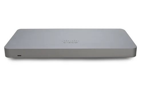
Use an MX75 at the property edge, an MS130-48P PoE switch and CW9172H wall-plate APs in the initial room layout. Use CW9172I APs for the lobby and restaurant. Keep property-management systems, staff access, payment equipment and guest traffic in separate networks.
Enable guest client isolation and agree how shared devices such as casting receivers are discovered without exposing other rooms. Count AP power requirements, uplink utilisation and the ISP circuit together.
Operating it day to day
Survey a representative occupied room and the rooms above and beside it before replicating the layout. Tune transmit power and channel reuse so AP density does not create avoidable contention.
Document the captive-portal support process and provide reception with a simple incident checklist: room, device, time and affected service. Schedule upgrades outside busy arrival periods and retain the previous configuration for rollback.
What to test before handover
- Walk a video call from reception to sample rooms and record any interruptions.
- Test casting discovery within one room and isolation from neighbouring rooms.
- Load-test the guest service while the PMS and a test payment remain usable.
- Confirm an unauthenticated guest cannot reach staff or device-management addresses.
Technical references
The bill of materials
Illustrative 12-room property with a lobby and restaurant. The room count is a planning example, not a coverage promise. Quantities below describe the example; your proposal confirms the final equipment and services.
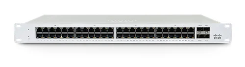
Cisco Meraki MS130-48P Cloud Managed 48-Port PoE Switch
MS130-48PRoom and common-area PoE
View product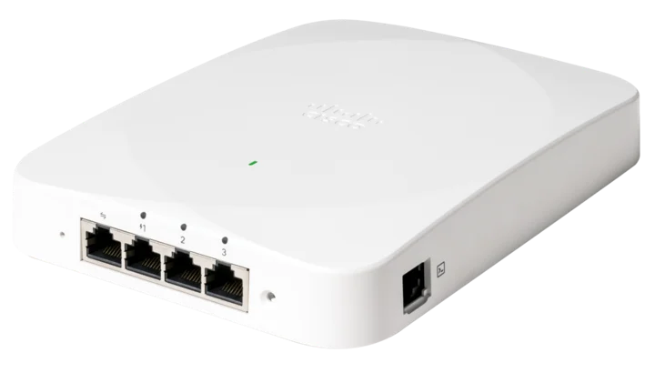
Cisco CW9172H wall-plate access point
CW9172H-CFGIn-room wireless access
One per room in the example; validate placement in the pilot rooms.
View product
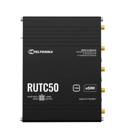
Teltonika RUTC50 5G router
RUTC50210000Cellular continuity
Optional — Protect property systems ahead of guest streaming.
View product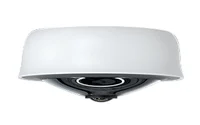
Cisco Meraki MV33 indoor fisheye camera
MV33Reception overview
Optional — Indoor camera with an agreed retention policy.
View productComplete the installation
The equipment above is one part of the project. Include these items in the final scope.
- Meraki licences
- Guest portal and casting integration
- Cabling, mounts, cabinet and UPS
- ISP and optional cellular service
Questions before you specify
Is one AP per bedroom always necessary?
No. Room construction and the survey determine the density. The example starts with one wall-plate AP per room so coverage and casting can be tested before ordering the full quantity.
Can staff and guests use the same access points?
Yes, with appropriately configured SSIDs, VLANs and firewall policy. Sharing radio hardware does not require sharing access to property systems.
Let’s design it for your site.
Send us the details below. We can turn the reference architecture into a scoped design, equipment schedule and quotation.
Start your projectBring these to the first conversation
- 01Room and floor plans
- 02Wall construction and existing cable outlets
- 03Peak occupied rooms and concurrent devices
- 04PMS, casting and payment-system requirements