
Solar telemetry with a dependable local record
Link inverter data and site alarms to remote operations while keeping plant control local and engineering access restricted.

Separate monitoring from plant control
Preserve readings through coverage gaps
Restrict remote engineering access
How the solution connects
Follow the data from collection to the people and services that use it.
Read the connection map
- Inverter data logger → RUTC50 or TRB246 · Collection
- Site alarms / serial I/O → RUTC50 or TRB246 · Collection
- RUTC50 or TRB246 → Monitoring platform · Protected transfer
- Monitoring platform → Operations dashboard · Workflow
- Monitoring platform → Alarm escalation · Workflow
- Monitoring platform → Restricted engineering · Workflow
The challenge on the ground
An inaccessible inverter dashboard does not necessarily mean a generation fault. The monitoring design must distinguish an equipment alarm from loss of the communications path.
Long field cable runs, exposed power systems and different inverter protocols make a generic office router installation unsuitable.
Inside the design
Use a RUTC50 for the site IP uplink where measured 5G/4G service supports the workload. A TRB246 provides a current Cat 4 gateway option for a separate serial/Ethernet telemetry point; choose it as an alternative collection path, not a mandatory second router.
Connect IP equipment with a TSW210 where additional ports are needed. Publish data through the logger or approved integration service, retaining a local timestamped record.
Operating it day to day
Keep inverter control and protection functions independent of the cloud connection. Permit engineering access only through an authenticated, restricted route and avoid public port forwards to controllers.
Specify outdoor enclosures, DC conversion, surge protection and grounding with the electrical design. Test data replay after an outage so the monitoring platform can distinguish missing readings from zero generation.
What to test before handover
- Remove cellular service and compare the local logger with the recovered cloud record.
- Trigger a safe test alarm and confirm the operations response.
- Verify that remote users cannot reach unapproved controller services.
- Inspect restart behaviour after controlled communications power loss.
Technical references
The bill of materials
One solar site with an existing data logger and either Ethernet or RS-485 equipment. Quantities below describe the example; your proposal confirms the final equipment and services.
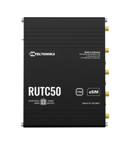
Teltonika RUTC50 5G router
RUTC50210000Site IP connectivity
For the Ethernet logger architecture.
View product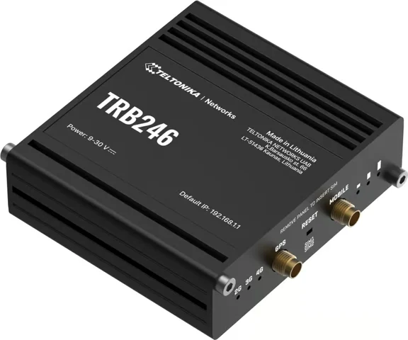
Teltonika TRB246 IoT gateway
TRB246000000Serial telemetry alternative
Alternative — Use instead of the main router at a low-volume serial collection point.
View product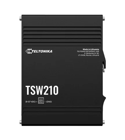
Teltonika TSW210 Industrial Ethernet Switch
TSW210000040Industrial Ethernet expansion
Optional — Unmanaged Ethernet expansion; power is separately supplied.
View productComplete the installation
The equipment above is one part of the project. Include these items in the final scope.
- Existing logger and protocol integration
- Protective enclosure, DC supply and surge protection
- Carrier plan and monitoring service
- External antenna and installation survey
Questions before you specify
Why not use the old TRB255?
TRB255 has ended production. This design offers current Cat 4 serial/Ethernet collection with TRB246; a Cat-M/NB-IoT TRB256 option requires a matching carrier network and telemetry requirement.
Let’s design it for your site.
Send us the details below. We can turn the reference architecture into a scoped design, equipment schedule and quotation.
Start your projectBring these to the first conversation
- 01Inverter/logger makes and protocols
- 02Available DC power and enclosure locations
- 03Carrier survey and data volume
- 04Alarm escalation and remote-access requirements