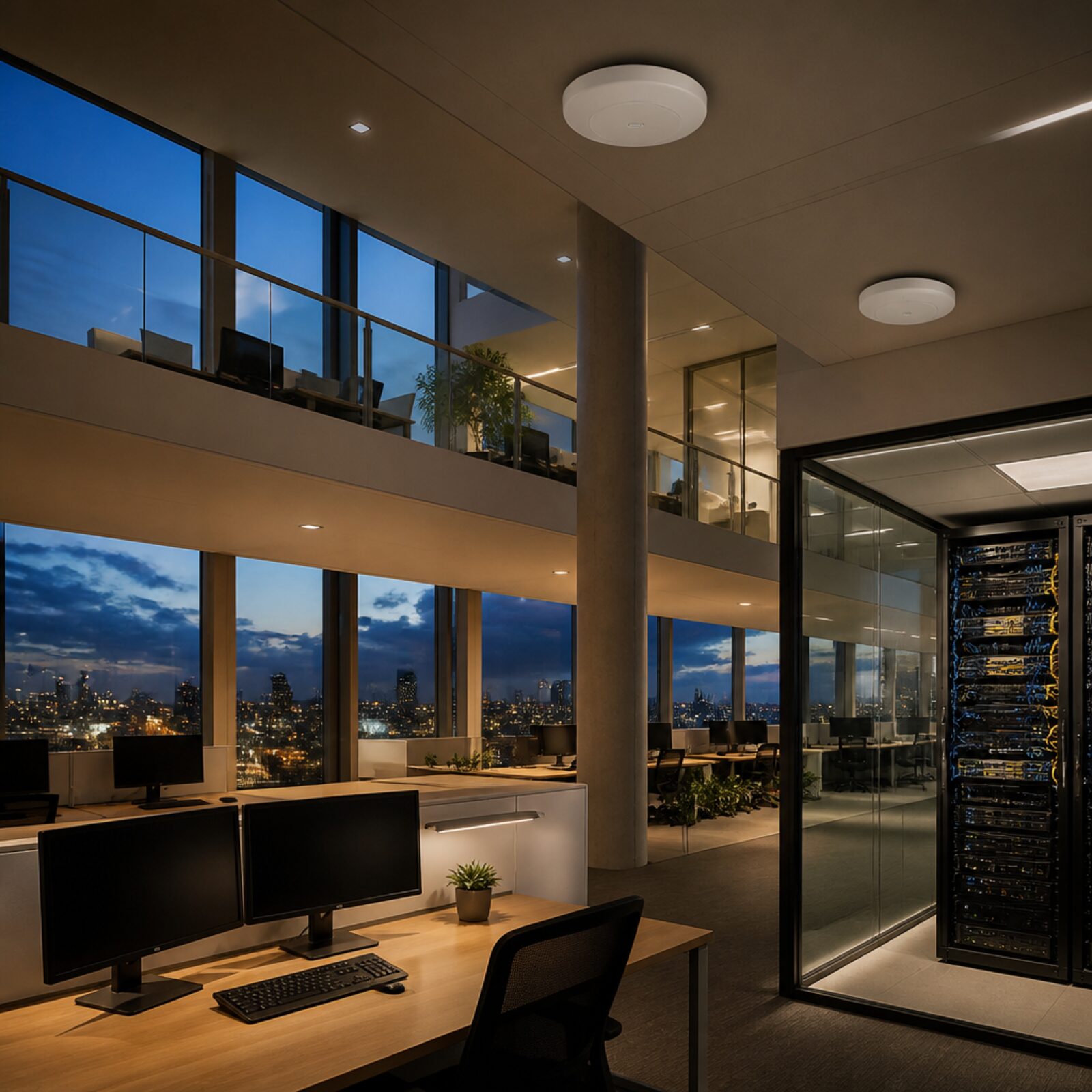
A tidy comms cabinet starts with the outlet plan
Plan office outlets, patching and rack space together, with a traceable cable schedule and room to maintain the installation.
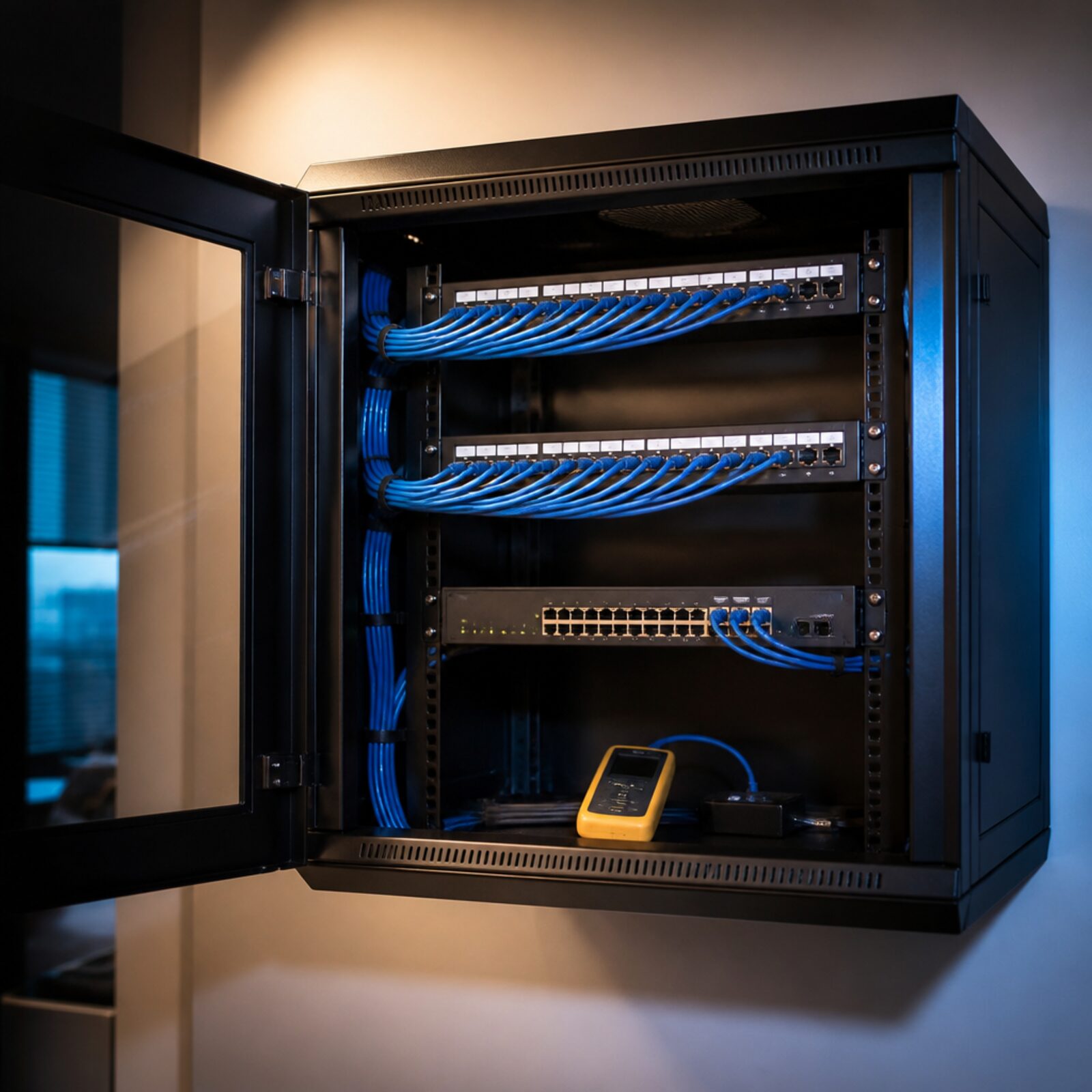
Match every outlet to a labelled port
Check physical fit before procurement
Leave a maintainable cabinet handover
How the solution connects
Follow the data from collection to the people and services that use it.
Read the connection map
- Desk + AP outlets → Cat6 patch panel · Collection
- Labelled permanent links → Cat6 patch panel · Collection
- Cat6 patch panel → Switch patching · scoped · Protected transfer
- Switch patching · scoped → Office devices · Workflow
- Switch patching · scoped → Wireless APs · Workflow
- Switch patching · scoped → Port schedule + tests · Workflow
The challenge on the ground
Buying a cabinet first often leaves too little usable depth, no space for patch leads or awkward access to power. An office cabling design should begin with desk, AP and device positions, then trace each outlet back to its termination and switch port.
The neat appearance comes from that plan, not from hiding spare cable behind equipment.
Inside the design
Use a Lanberg PPU6-1024-B equipped 24-port Cat6 UTP patch panel with a compatible 19-inch WF01-6406-10B wall cabinet in the example. The panel uses IDC/LSA terminations; it is not a keystone carrier.
Specify matching cable and outlet components for the agreed channel design. Check active-equipment depth, patch-lead clearance, ventilation, load and wall fixing before approving the six-unit cabinet.
Operating it day to day
Create a room/outlet/panel schedule and use it for labels at both ends. Separate power and data routes according to the installation design, maintain bend radius and support cable bundles without crushing them.
Keep test records for each installed link and photographs of the finished terminations. Reserve space for cable management, a PDU and future changes; choose a larger enclosure if the active equipment or UPS needs it.
What to test before handover
- Reconcile all outlet labels with the panel and drawing schedule.
- Test each installed link to the agreed cabling specification.
- Check door closure, patch-lead clearance and ventilation with equipment installed.
- Hand over test results, spare capacity and the cabinet elevation.
Technical references
The bill of materials
Example small office with up to 24 copper outlets and a compact wall cabinet; active equipment must fit the usable depth and thermal budget. Quantities below describe the example; your proposal confirms the final equipment and services.
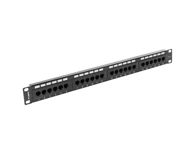
Lanberg 24-port Cat6 UTP patch panel
PPU6-1024-B24-port Cat6 termination
Equipped UTP panel with IDC/LSA terminations.
View product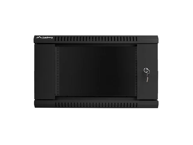
Lanberg 19-inch 6U wall cabinet
WF01-6406-10B19-inch 6U wall cabinet
Approve usable depth, wall fixings and heat/load budget before ordering.
View productComplete the installation
The equipment above is one part of the project. Include these items in the final scope.
- Installation cable and matching outlets
- Patch leads, cable management and labels
- PDU and any appropriately housed UPS
- Active switch, installation and link certification
Questions before you specify
Will any 19-inch device fit this cabinet?
No. Rack width is only one dimension. Check usable depth, rear connections, load, ventilation and service access.
Do we need keystone modules for this panel?
This selected panel is equipped for IDC/LSA termination. A modular keystone design requires a different compatible panel and matching modules.
Let’s design it for your site.
Send us the details below. We can turn the reference architecture into a scoped design, equipment schedule and quotation.
Start your projectBring these to the first conversation
- 01Floor plan and outlet schedule
- 02Cable routes and installation conditions
- 03Active-equipment dimensions and load
- 04Wall construction, power and growth allowance