
Tender connectivity with a clear service boundary
Connect a tender’s crew and operational devices using a compact WAN design that can change transport as the vessel moves.

Account for changing coverage and power
Separate crew access from vessel devices
Plan tunnel and satellite eligibility
How the solution connects
Independent uplinks meet a controlled network boundary. Local access is separated by purpose.
Read the connection map
- Starlink Mini WAN → Peplink MBX Mini · Primary path
- Cellular transport → Peplink MBX Mini · Alternate WAN
- Peplink MBX Mini → Compact managed switch · Policy boundary
- Compact managed switch → Crew internet · Separate zone
- Compact managed switch → Operational devices · Separate zone
- Compact managed switch → Protected support access · Separate zone
The challenge on the ground
A tender has limited power and mounting space, and its route can move quickly between shore coverage and open water. A portable satellite terminal is useful only with the right service eligibility and a secure installation.
Neither Wi-Fi nor cellular connectivity should be confused with safety-critical maritime communications.
Inside the design
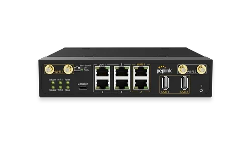
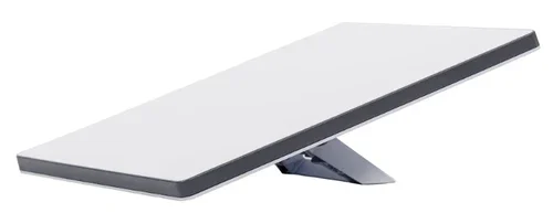
Use a Peplink MAX MBX Mini with the selected cellular configuration and a Starlink Mini Ethernet transport where the plan permits the intended operation. Add FusionHub for the agreed SpeedFusion tunnel workflow.
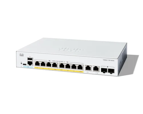
Keep crew internet separate from operational devices through a compact managed switch. Antenna selection follows the modem bands, connector arrangement and mounting geometry; it is not a separate cellular WAN by itself.
Operating it day to day
Confirm power consumption, start-up behaviour and battery protection with the vessel electrical design. Keep antenna cable runs short and protected, and test around the actual operating route.
Limit nonessential traffic on constrained services. Document which onboard systems remain available locally and who takes action when all internet transports are unavailable.
What to test before handover
- Test coverage and tunnel behaviour on a representative approved route.
- Check battery load and controlled restart.
- Fail the satellite and cellular transports independently.
- Verify crew isolation from the operational network.
Technical references
The bill of materials
One tender with protected equipment space and an existing onboard operational network. Quantities below describe the example; your proposal confirms the final equipment and services.
Starlink Mini
SLK-MINISatellite transport option
Confirm service eligibility for the intended location and movement.
View product
Complete the installation
The equipment above is one part of the project. Include these items in the final scope.
- Compatible marine antenna system
- Satellite and carrier plans
- DC conversion, fusing and sealed cabling
- Endpoint hosting and required licences
Questions before you specify
Can this replace marine safety communications?
No. This is an internet connectivity design. Safety and navigation communications remain separate approved systems.
Let’s design it for your site.
Send us the details below. We can turn the reference architecture into a scoped design, equipment schedule and quotation.
Start your projectBring these to the first conversation
- 01Operating area and vessel motion
- 02Power and protected mounting space
- 03Modem/antenna and satellite service requirements
- 04Onboard applications and support responsibilities


